HALO-(AC )3
Arctic Air Mass Transformations During Warm Air Intrusions And Marine Cold Air Outbreaks
Mission status: Completed
Mission Website:
Persons in Charge
Mission-PI
Manfred Wendisch, Leipzig University, Leipzig Institute for Meteorology (LIM)
Scientific Co-Leadership
Susanne Crewell, University of Cologne, Institute for Geophysics and Meteorology (IGM)
Mission coordinator
André Ehrlich, Leipzig University, Leipzig Institute for Meteorology (LIM)
Contact point at DLR-FX for this mission:
HALO Project Management: Philipp Nguyen, Andreas Minikin
Postal address:
DLR Oberpfaffenhofen
Flugexperimente (FX)
Projektmanagement
Münchener Str. 20
82234 Weßling
Germany
Office phone:
+49 (0)8153 28-2906
HALO Deployment Base
Time Period
December 2021 – April 2022
| Mission phase | Dates |
|---|---|
| Preparation, payload integration, EMI testing | 13 Dec 2021 - 12 Mar 2022 |
| Mission execution | 12 Mar - 15 Apr 2022 |
| Dismounting of payload | 19 - 22 Apr 2022 |
Project description
Currently, the Arctic climate is changing at an unprecedented pace and intensity. As an example, a remarkable increase of the Arctic near-surface air temperature has been observed starting about 25 years ago, which exceeds the global warming at least by a factor of two. This phenomenon is commonly referred to as Arctic amplification. The excessive Arctic warming, which is projected to progress during the 21st century, is both a consequence and a driver of feedback processes specific to the Arctic. These interlinked feedback mechanisms cause further partly dramatic climate changes in the Arctic, such as the stronger-than-expected decline of the Arctic sea ice observed since about 1970 and other phenomena. The feedback processes are driven by Arctic-specific and unique conditions, such as pronounced temperature inversions close to the ground, heterogeneous surface properties (open ocean, sea ice), and persisting low-level clouds (often mixed–phase). In addition, there are coupled local feedback mechanisms (surface albedo, water vapour, cloud, lapse rate, and Planck feedback processes), which appear particularly effective in the Arctic. Furthermore, remote feedback processes seem to link the Arctic and the mid-latitudes by meridional transport of heat, humidity, and momentum.
Arctic amplification might cause a weaker jet stream, which would result in an increase of undulations (wavier jet), an amplification of Rossby wave amplitudes, and more blocking situations. Thus, meridional transports of air-masses would occur more frequently, connecting the Arctic and mid-latitudes more closely. There are two major types of meridional air-mass transport: Poleward warm/moist air intrusions into, and southward cold/dry air outbreaks out of the Arctic. An increased occurrence of warm air intrusions and cold air outbreaks would further amplify the Arctic warming (positive feedback). However, these seemingly comprehensible chains of processes are debated. The only way to verify such feedback mechanisms is by using models. Unfortunately, climate models suffer from specific deficiencies, in particular with regard to air-mass transformation processes along the meridional transport pathways, which may trigger additional local feedback mechanisms, such as cloud formation and boundary layer development. For example, show that most climate models lack a realistic representation of the cloudy state and that the misrepresentation of mixed-phase clouds causes climate model biases in Arctic wintertime temperature inversions.
So far, observations of air-mass transformations in the Arctic have mostly been conducted from a fixed location. Only few aircraft-based samplings of air-mass properties over a limited regional area have been reported. This Eulerian point of view does not permit the observations of air-mass modifying processes along their meridional pathway, which are required for model validations. Therefore, we are proposing a quasi-Lagrange approach following air-masses to and from the Arctic to observe the air-mass transformation processes during warm air intrusions and cold air outbreaks, whereby we focus on warm air intrusions, which are less extensively documented in literature. This quasi-Lagrange approach requires a long-endurance airborne facility, which may carry the necessary equipment for the observations. HALO with its exceptional endurance and high lifting capacity is most suited for these observations.
The HALO campaign studying air-mass transformations in the Arctic is combined with the Transregional Collaborative research Centre SFB/TR 172 (http://www.ac3-tr.de/), called (AC)³, which investigates and evaluates major atmospheric and surface processes and feedback mechanisms causing Arctic amplification. Therefore we refer to this HALO campaign as to HALO–(AC)³ in the following.
HALO will be based in Kiruna (northern Sweden), and the campaign will take place between 12 March and 15 April 2022. The instrumentation will be installed in Oberpfaffenhofen (December 2021 to March 2022). After obtaining the necessary permissions, HALO will be transferred to Kiruna and perform measurements over a period of five weeks with altogether 142 flight hours (including test flight, EMV certification flight, and transfer to Kiruna). HALO will return to Oberpfaffenhofen in April 2022.
The general objectives of the HALO–(AC)³ mission are:
(i) To perform quasi-Lagrange observations of air-mass transformation processes during meridional transports with a particular focus on pronounced warm air intrusions and marine cold air outbreaks, and
(ii) To test the ability of numerical atmospheric models to reproduce the measurements, which then can be applied to investigate the linkages between Arctic amplification and mid-latitude weather.
Figure 3.27 illustrates the intended observational strategy to achieve the general objective (i). We will observe the transformation processes of air-mass properties along their poleward pathways over the open water, the marginal sea-ice zone (MIZ), and the sea ice of the Arctic Ocean during warm air intrusions. Vice versa, we will sample the air-mass transformations during southward marine cold air outbreaks from the sea ice, crossing the MIZ, and then moving over the open ocean water. HALO is capable to carry a state-ofthe- art set of meteorological and remote sensing instruments (up to 3 t) high enough (up to 15 km) to observe the complete vertical tropospheric air-mass column, including meteorological quantities, turbulence parameters, water vapour, aerosol particles, and clouds. Furthermore, the long endurance of HALO allows to base HALO operations in Kiruna.
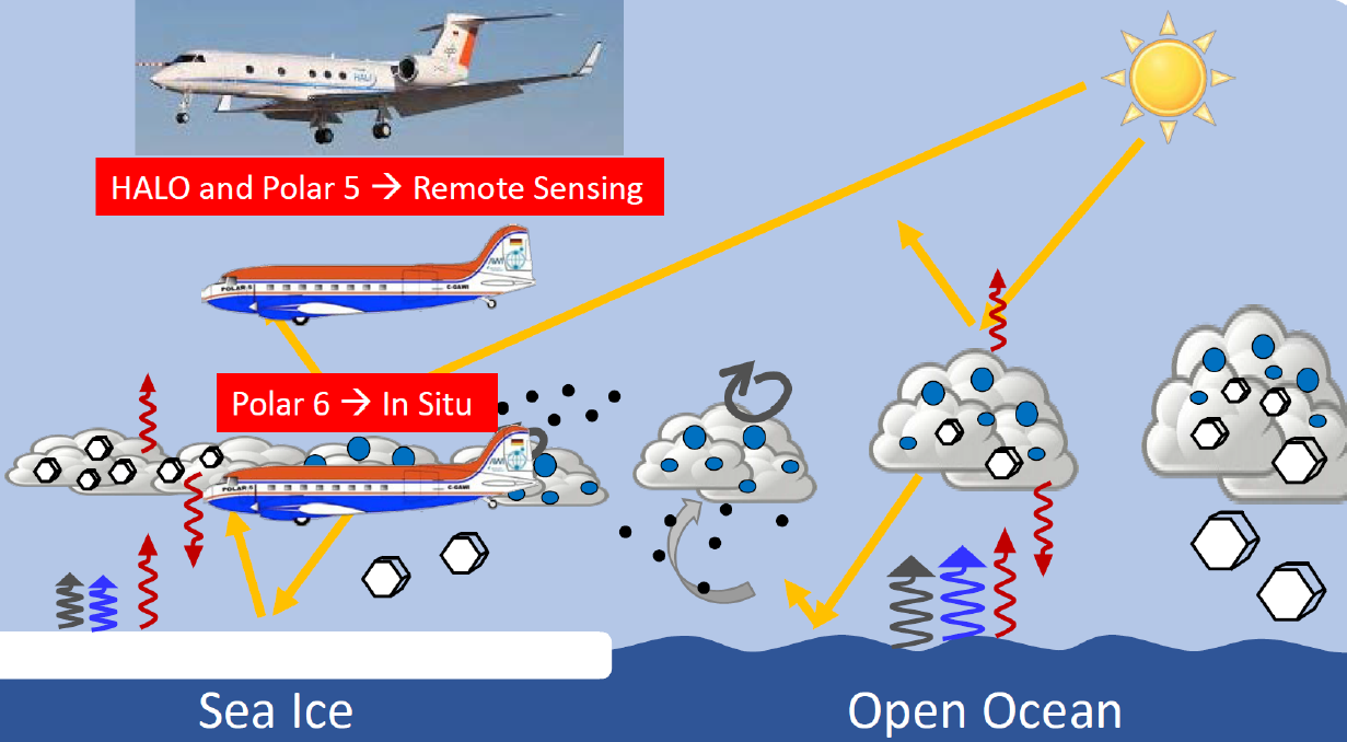
Figure 3.27: Strategy of the HALO–(AC )3 campaign, jointly with Polar 5 and Polar 6 aircraft from AWI.
In addition, we will operate (in close collocation with HALO) two further low-flying aircraft (Polar 5: Active and passive remote sensing measurements; and Polar 6: In situ measurements of clouds, aerosol particles, and radiation) funded by AWI to probe smallerscale processes in the lower troposphere (below 3-5 km altitude) in a similar coordinated way as done during the ACLOUD campaign. The data collection and analysis of the AWI aircraft data, as well as part of the HALO–(AC )3 data analysis, will be realized within the SFB/TR 172.
General objective (ii) will be pursued by building case studies based on the measurements, for which the effects of distance to the ice edge, ice concentration, and topography will be investigated. The observations during HALO–(AC )3 will provide unique data to evaluate the output of numerical atmospheric models covering a wide range of spatial (columnar to Arctic-wide) and temporal (instantaneous to several days) scales, from columnar Lagrange (Large Eddy Simulation) to meso-scale Eulerian atmospheric models. For example, an LES will be run moving with Arctic air-masses that will be sampled by HALO at multiple points in their life cycle. Using the measurements from HALO–(AC )3, sensitivity studies to isolate important individual processes will be performed. SFB/TR 172 will significantly contribute to achieve the general objective (ii).
The observations will be realised by measurements of vertical profiles of:
- Meteorological parameters (humidity, temperature) with dropsondes, lidar, and mi- crowave radiometer,
- Aerosol properties (extinction coefficient) using lidar,
- Cloud parameters (thermodynamic phase, LWP, IWP, optical thickness, effective droplet radii, spectral albedo, cloud top altitude, vertical extent) with an EarthCARElike remote sensing package including radar, lidar, microwave radiometer, solar spectral radiometers and imaging solar spectrometers, and
- Energy budget including radiation irradiances using broadband solar and terrestrial radiometers, and turbulent fluxes using the nose boom instrumens.
Dropsonde measurements are crucial for the project. HALO is capable to release dropsondes from high altitudes and in high temporal resolution. They provide accurate in situ measurements and can be released into hazardous environments (e.g., mixed-phase, icing clouds). The measurements with dropsondes include data of wind, temperature, and humidity in an almost perfect vertical profile since the horizontal drift of the drops during their fall (about 10 min fall time) is mostly not larger than about 1 to 10 km. The horizontal speed of the aircraft does not allow to measure strictly on vertical profile patterns. As a consequence, dropsonde measurements are indispensable components for atmospheric profiling using aircraft. Series of dropsonde releases will help to construct vertical cross-sections of temperature, wind, and humidity (including clouds) between the surface and flight level of the aircraft along its track. This will enable to investigate the typical flow regimes in the Arctic.
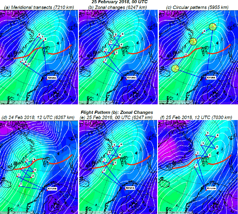
Figure 3.28: Possible flight tracks. (a) Meridional transects, (b) Zonal changes, (c) Circle patterns
(yellow). The red lines indicate the average sea ice boarder expected for beginning of April, during
HALO–(AC )3. (d) to (f) show a scenario of consecutive flight tracks.
Flight transects are intended to follow an air parcel for at least three consecutive days, and to retrieve the parcel every day. Possible scenarios are illustrated in Figure 3.28. We will track thermodynamic, cloud, and aerosol characteristics along (Figure 3.28 a) and perpendicular (Figure 3.28 b) to the streamlines (trajectories). Dropsonde releases during circular flight pattern (Figure 3.28 c) will serve to obtain large-scale vertical motion. The consecutive tracking of air-masses is schematically illustrated in Figures 3.28 d-f.

Figure 3.29: Flight planning including air parcel trajectory forecast, see https://www.atmos.
washington.edu/\simjkcm/CSET_plots/GOES_loops/rf06_rf07_12fps_boxes.mp4
Additionally, Figure 3.29 depicts how trajectory predictions will be used in the flight planning. We will follow a strategy developed within the Cloud System Evolution in the Trades (CSET) project, see http://cseteducation.weebly.com/. Figure 3.29a shows the flight path at the beginning of the observations (blue line). Consecutive flight paths will be performed involving the temporal movements of the individual air parcels (indicated as coloured squares). It will be crucial for the flight planning to involve modelling groups to provide predicted trajectories of the air parcels to be sampled. The strategy is to meet and sample the air parcel along its trajectory as often as possible. This requires sophisticated modelling during the HALO–(AC )3 campaign.
Partners
- Leipzig University, Leipzig Institute for Meteorology (LIM)
- Alfred Wegener Institute Helmholtz Centre for Polar and Marine Research (AWI)
- German Aerospace Center, Institute of Atmospheric Physics (DLR-IPA), Oberpfaffenhofen
- Laboratoire de Météorologie Physique France (LaMP)
- Leibniz Institute for Tropospheric Research (TROPOS), Leipzig
- Max Planck Institute for Chemistry (MPIC), Mainz
- Max Planck Institute for Meteorology (MPI-M), Hamburg
- Institute of Environmental Physics (IUP)
- Universität Hamburg, Meteorological Institute (MI)
- University of Cologne, Institute of Geophysics and Meteorology (IGM)
- Ludwig-Maximilians-Universität München (LMU), Meteorological Institute Munich (MIM)
Scientific instruments and payload configuration
List of scientific instruments for the mission:
| Scientific instrument acronym | Description | Principal investigator |
|---|---|---|
| HAMP Cloud Radar | The radar is a nadir staring instrument that measures in the water-vapor window at a frequency of 35.5 GHz (Ka-band). This system, similar to cloud radars operated on the Barbados Cloud Observatory, is operated with a 200 ns pulse length and a pulse repetition frequency of 5kHz. Two receivers provide co- and cross-polarization reflectivity measurements. | Lutz Hirsch (MPI-M) |
| HAMP Radiometer | Three downward looking radiometer modules passively measure the microwave emissions of Earth’s atmosphere in twenty-six channels probing two water vapor and two oxygen absorption features, as well as window channels. Beam widths of 2.7º to 5.0º and a sampling rate of about 1 s. | Friedhelm Jansen (MPI-M) |
| WALES Lidar | WALES operates at four wave-lengths near 935 nm to measure water-vapor mixing ratio profiles covering the whole atmospherebelow the aircraft. At typical flight speeds it has a resolution of 200 m in the vertical and 6 km in the horizontal. The system also contains additional aerosol channels at 532 nm and 1064 nm with depolarization. WALES uses a high-spectral resolution technique, which distinguishes molecular from particle backscatter, to make direct extinction measurements with a resolution of 15 m in the vertical and 200 m in the horizontal.
| Martin Wirth (DLR-IPA) |
| SMART | The Spectral Modular Airborne Radiation measurement sysTem (SMART) measures spectral irradiances from zenith and nadir oriented sensors. An additional nadir looking sensor measures radiances. Measurements span the visible and near infrared (300 nm to 2200 nm) with a 2 nm to 3 nm spectral resolution for wavelengths shorter than 1000 nm and a 10 nm to 15 nm spectral resolution for longer wavelengths. | André Ehrlich (Leipzig Univ.) |
| specMACS | The spectrometer of the Munich Aerosol Cloud Scanner (specMACS) consists of two camera systems, both looking nadir, one in the visible/near-infrared (400 nm to 1000 nm), and another in the short-wave infrared (1000 nm to 2500 nm). The systems produce a spectrally resolved line image with 1312 pixels covering a 32.7º field of view in the visible/near infrared, and with 320 pixels covering a 35.5º field of view in the short-wave infrared. | Tobias Zinner, Veronika Pörtge (LMU München) |
| VELOX | A broadband camera system with a filter to take broadband (7.7 μm to 12 μm) and narrow band images near 8.6μm, 10.8 μm; 11.6 μm; and 12 μm. The camera has 640x512 spatial pixesl for a 21.7° x 17.5° field of view. This gives roughly 6m by 6m spatial resolution for a target at 10 km distance. The camera operates betwen -60ºC and 100ºC with a sensitivity better than 0.05 K. | Michael Schäfer (Leipzig Univ.) |
| Dropsondes | AVAPS dropsonde system using Vaisala RD-94 sondes to measure temperature with an accuracy of 0.2 ºC, humidity with an accuracy of 2 %RH, pressure with an accuracy of 0.4 hPa. Winds are derived from GPS position measurements with an estimated accuracy of 0.1 m/s. The receiver can track four sondes simultaneously. For the measured descent time of about 750 s from a drop altitude of 9.5 km, the capability of the receiver allows a sonde to be launched roughly every three and a half minutes. Anna | Lübcke, (Leipzig Univ.) |
| BAHAMAS | Aircraft state variables, position, three-dimensional turbulent winds (from five hole probe on boom), humidity (diode laser), temperature and pressure. | Andreas Giez (DLR-IPA) |
| BACCARDI | Broadband radiometers for downwelling and upwelling irradiances in both the SW (< 4 μm) and LW parts of the spectrum. | Andreas Giez (DLR-IPA) André Ehrlich (Leipzig Univ.) |
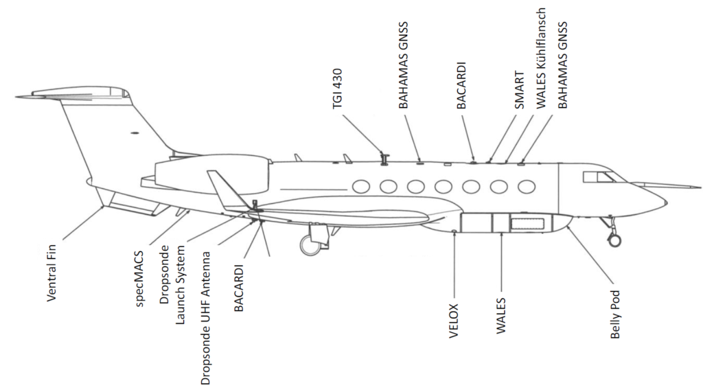
Cabin and exterior configuration of HALO for the mission

HALO flights for this mission
| Aircraft registration | Date | Take off - Landing / UT | Total flight time / h | From - To | Mission # |
|---|---|---|---|---|---|
| D-ADLR | 2022-02-25 | 07:31:06 - 12:12:27 | h | CODE - CODE | RF00 |
| D-ADLR | 2022-03-11 | 13:19:28 - 16:22:31 | h | CODE - CODE | RF01 |
| D-ADLR | 2022-03-12 | 08:22:06 - 16:44:07 | h | CODE - CODE | RF02 |
| D-ADLR | 2022-03-13 | 08:04:31 - 16:52:50 | h | CODE - CODE | RF03 |
| D-ADLR | 2022-03-14 | 08:45:34 - 17:19:08 | h | CODE - CODE | RF04 |
| D-ADLR | 2022-03-15 | 09:04:50 - 17:46:50 | h | CODE - CODE | RF05 |
| D-ADLR | 2022-03-16 | 08:58:18 - 18:27:20 | h | CODE - CODE | RF06 |
| D-ADLR | 2022-03-20 | 07:58:48 - 17:07:05 | h | CODE - CODE | RF07 |
| D-ADLR | 2022-03-21 | 08:48:45 - 16:35:38 | h | CODE - CODE | RF08 |
| D-ADLR | 2022-03-28 | 08:38:36 - 16:06:06 | h | CODE - CODE | RF09 |
| D-ADLR | 2022-03-29 | 07:53:09 - 16:27:06 | h | CODE - CODE | RF10 |
| D-ADLR | 2022-03-30 | 07:56:46 - 16:21:08 | h | CODE - CODE | RF11 |
| D-ADLR | 2022-04-01 | 07:29:57 - 15:40:34 | h | CODE - CODE | RF12 |
| D-ADLR | 2022-04-04 | 07:26:01 - 16:18:02 | h | CODE - CODE | RF13 |
| D-ADLR | 2022-04-07 | 08:33:00 - 16:14:47 | h | CODE - CODE | RF14 |
| D-ADLR | 2022-04-08 | 04:25:13 - 11:43:45 | h | CODE - CODE | RF15 |
| D-ADLR | 2022-04-10 | 09:54:45 - 16:25:05 | h | CODE - CODE | RF16 |
| D-ADLR | 2022-04-11 | 07:55:53 - 15:55:48 | h | CODE - CODE | RF17 |
| D-ADLR | 2022-04-12 | 07:30 - 15:32 | h | CODE - CODE | RF18 |
More information
Press releases, media etc
Can be found here: https://halo-ac3.de/halo-ac3/international-press/